
Goa Residence — Electrical & Plumbing MEP Project Profile
This project profile is based on EENOKI’s documented proposal and issued electrical drawing records for a residential project in Goa. It presents only verified scope and design evidence and does not claim project completion or publish client-confidential drawings.
Exterior architectural visualization of the Goa residence.
These are actual 3D exterior views supplied for this project. They provide architectural context for the MEP project profile; EENOKI’s role on this page is MEP design and consultancy.


These newly supplied architectural 3D views are the current public project visuals for the Goa residence. EENOKI’s verified MEP design evidence is presented separately below.
Project context
EENOKI’s proposal dated 17 March 2026 identifies the project as a proposed residential project in Goa. The documented consultancy scope included Electrical system design and Plumbing system design, together with preparation of drawings, schematic diagrams and schedules, site visits for clarification, MEP documentation, advisory assistance and technical guidance.
Later electrical drawing records dated 21 August 2026 identify the project as Residence at Goa, confirming that the project progressed into detailed electrical documentation.
Documented Electrical design scope
The project proposal records a detailed electrical and lighting scope that included:
- Assessment of electrical loads.
- Selection of protection equipment.
- Interior, exterior and landscape lighting design.
- Distribution Board and electrical panel design.
- Cable and feeder selection considering short-circuit and voltage-drop requirements.
- Cable-tray and conduit routing.
- Power-supply layout preparation.
- CCTV and other ELV layout preparation.
- Electrical power-distribution schematic diagrams.
- Bill of Quantities, tender documentation and material specifications.
Electrical drawing evidence
The available drawing package shows that the project documentation developed beyond a basic power-point layout. The records include general installation details, earthing details, power and lighting information, distribution-board schedules and several ELV and future-service provisions.
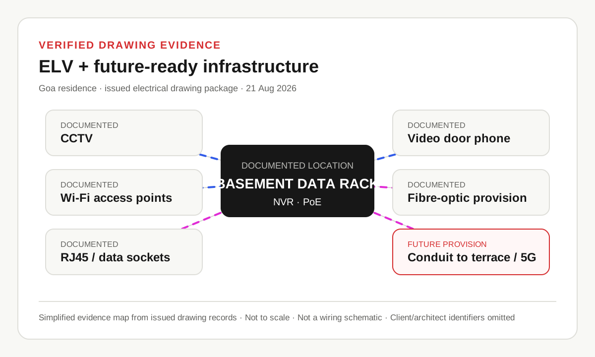
Examples visible in the issued drawings include CCTV, data sockets, TV points, Wi-Fi routers and access points, video door-phone provisions, an NVR/data-rack area, a continuous conduit route toward the terrace for a future 5G antenna, fibre-optic provisions, landscape/garden distribution, and a provision associated with a solar energy meter.
This combination illustrates the coordination requirement in a modern residence: power, lighting, ELV, outdoor services, future technology and earthing all need to be considered together rather than added one by one at the end.
Documented Plumbing design scope
The proposal also records Plumbing design as part of EENOKI’s scope. The planned services included:
- Cold-water supply design.
- Hot-water supply design.
- Stormwater-system design.
- Pipe sizing and routing.
- Water-supply layout drawings.
- Drainage pipe selection and routing.
- Manhole positioning according to site orientation and levels.
- Drainage-system layout drawings.
- Bill of Quantities, tender documents and material specifications.
Planned project workflow
The proposal describes a staged design process beginning with meetings and project-requirement discussions, followed by preliminary drawings for review, final drawings after design feedback, and further technical coordination through the project where required.
This workflow is important because coordinated MEP design is iterative. Architectural information, equipment requirements and service interfaces need to be reviewed before the final documentation is frozen.
Visual evidence from the documented design
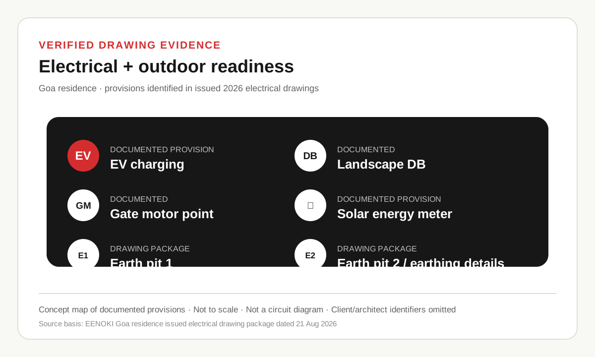
The actual project-supplied architectural 3D views are shown above. The technical visuals below remain simplified evidence maps so the page can demonstrate verified MEP provisions without reproducing the client’s architectural floor plan or drawing title block.
Verified design decisions visible in the issued drawings
The issued electrical package contains several concrete design decisions that show how the residence was planned beyond basic power and lighting:
- Future communication pathway: a continuous conduit is shown from the ground-floor NVR area to the terrace for a future 5G antenna.
- Data infrastructure: the drawings identify a basement data rack for NVR and PoE equipment together with RJ45/data, Wi-Fi, CCTV and fibre-optic provisions.
- Video-door-phone coordination: indoor and outdoor VDP provisions are included within the ELV layouts.
- EV readiness: EV charging is identified in the electrical documentation rather than being left as an afterthought.
- Landscape and outdoor loads: dedicated landscape distribution-board references and gate-motor provisions are documented.
- Solar metering readiness: the drawings include a provision associated with a solar energy meter.
- Earthing: a dedicated earthing-details sheet is part of the issued package.
These are useful examples of a design-stage approach that anticipates future technology, outdoor services and maintainability while the concealed routes can still be coordinated.
What this project demonstrates
The strongest verified lesson from the available records is the value of planning Electrical, Plumbing and ELV requirements as part of the same design process. The electrical package alone contains power distribution, lighting, earthing, CCTV, network, Wi-Fi, video-door-phone, future communication provisions and outdoor-service requirements.
For a residence, these systems become much easier to integrate when conduits, equipment locations, DBs, racks and future pathways are decided while the building is still in the design and construction stage.
Related EENOKI services and guides
Share the project stage and the MEP services you need.
Send the project location, approximate area, current stage, required services and the latest architectural plan if available.